 When designing a medical device made of complex, multi-functional mutually interacting subsystems it’s best to de-risk those subsystems instead of coming up with a paper design, assembling it, and hoping it works first time. De-risking individual subsystem behaviours one at a time enables more-focused assessments and improves troubleshooting.
For an optical subsystem, this de-risking is often conveniently performed using optical breadboards or cage systems – the optical-prototyping equivalent of LEGO® or TINKERTOY®.
Breadboards are usually not required for a simple camera system. But for more-complex imaging systems, therapeutic optical devices, or laser-based systems, breadboarding is an invaluable way to test out design ideas without the expense of machining or otherwise assembling the final product. This blog shares ten tips for progressing a breadboard system from roughly assembled components to a well-aligned optical subsystem prototype.
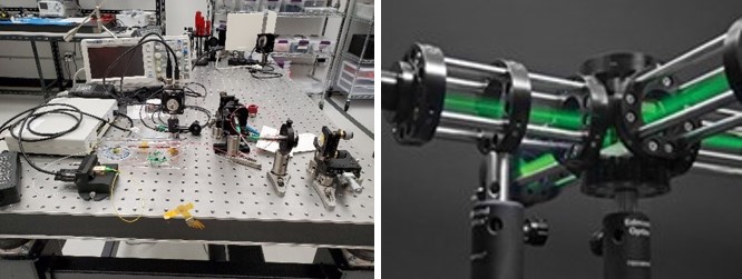 Figure 1: (a) an optical breadboard with components arranged for “proof-of-concept” testing (b) a typical optical “cage” system. (a) Photo Source: StarFish Medical (b) Photo Source: Edmund Optics
1. Be safe!
Before you set up your illumination and/or prober or treatment light sources, perform a safety assessment to quantify the hazards. Many optical medical devices are eye- and skin-safe. However, it’s worth remembering that medical device design often consists of balancing risk of harm with capacity for good. This is particularly true of optical therapeutic devices, but also can pertain to diagnostic instruments.
Familiarize yourself with the potential hazards. This is particularly important if there are light sources producing ultraviolet or infrared light. This radiation is invisible and many of your eye’s evolved safety reflexes will not be triggered by such light. Standard references for eye hazard limits are discussed in my earlier blog, “Incoherent-Light Hazard Classification for Medical Devices” Understand the power levels and wavelengths used and wear safety glasses as applicable.
Pay attention to intermediate focal points in the system: remember that the power density scales as the square of the beam diameter! If there are potentially hazardous light levels, be aware of spurious reflections and reflective jewelry (hands, wrist, and neck).
2. Have an understanding of what you expect the signal to look like once the prototype is assembled. Consider how you expect the signal to be affected when adjustments are made.
As I discussed in “Five recommendations for approaching medical device optics projects “, think about how the prototype should behave before you construct it. It’s not about running yet another raytrace – but rather about developing an intuition for the underlying behavior. Even if your intuition is incorrect, you will still have built the intellectual framework to analyze what’s actually happening.
3. Build an appropriate number of adjustments into your prototype.
Ensure that you have independent adjustments of key optical configurations (e.g. optics angles and/or x, y, z locations). Adjustable off-the-shelf mirror and/or lens mounts offer a convenient way to do this at the prototype stage. However, as you develop intuition about your design (see Point 2., above), ensure that you understand which actuators affect which characteristics of your optical beam.
Having a lot of degrees of freedom on the table doesn’t mean you have to use them. The dimensionality of your alignment space increases with every knob you turn, and woe be to you if you adjust knobs that are redundant with each other in their purpose! Adjust the minimum number of individual knobs appropriate to the alignment you are performing and leave the rest alone.
4. Make sure the power is on…
Optical prototypes have a somewhat “Frankenstein’s Monster” nature to them, and they will only work if the various power supplies and optical sources are powered up and connected properly. It’s worth double- and triple-checking that the various electrical connections to light sources and detectors are hooked up – and hooked up correctly! – before looking for where the light beams are going! The same advice goes for optical fiber interconnects in your prototype system.
5. Roughly align by geometry.
Some aspects of prototype design will be informed or constrained by optical design (e.g. focal distances, light-source locations). But there is often freedom to rearrange the orientation of various “optically active” components by bending the beamline with mirrors to fit the space available on the optical breadboard. It is convenient to set up mounts on 1” (2.5 cm) grid on the optical breadboard, at 0°, 45°, 90°, 180° angles, so long as critical distances along the optical beamline(s) are respected.
Use rulers, index cards, straight edges, laser pointers, etc. to get optical components in their approximate locations and at the appropriate separations. For rough layout, the human eye is a surprisingly accurate meter, and human hands are not horribly inaccurate alignment jigs. For example, with some practice, your eye can often spot non-concentricities of e.g. a bright, round beam and a circular target as small as 200 µm. If you use one hand to adjust and the other hand as a sort of “restoring force spring,” you can often align to a target to within 500 µm. If you’ve bent the beamline (even temporarily) to bring the target close to your body, then that’s an angular accuracy of better than 0.06° or 3.6’, at a viewing distance of 50 cm.
6. Perform a “next order” alignment at low optical power.
If the system uses optical powers that are both safe and comfortable for the eye, then you can operate at the use-case power level for the next level of alignment. Otherwise, operate at the lowest optical power that enables you to see the beam (directly or indirectly), always paying attention to the hazard levels. Ask yourself the following questions:
-
- Is the beam travelling along the appropriate path? a) If there are optical fibers in the design, is any light making it through the fibers?
- Is the beam center in the correct location with respect to the individual optical components?
- Is the transverse beam shape roughly correct?
- Are the foci where they should be?
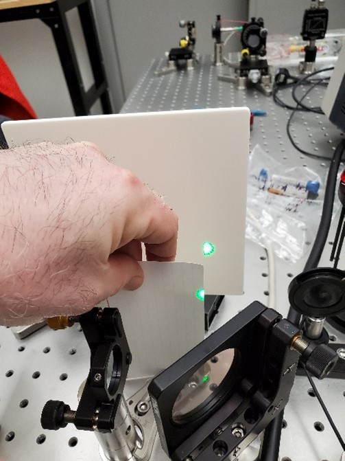 Figure 2: Using an index card to trace a green laser beam on an optical table. By looking for the point at which the unblocked beam has maximum diameter, one can locate the centroid of the laser beam with reasonable accuracy. Photo Source: StarFish Medical
Handy hint: the following methods are convenient to visualize the beam:
i. Visible: Use a paper index card (and PPE, as appropriate) to visualize the beam location.
ii. UV: Use a fluorescent address label or a highlighter.
iii. IR: Use special cards or an appropriate IR viewer.
UV & IR: As an alternative to using special cards or viewers, you can direct a low-power visible beam along the beam path and use that as an alignment guide. Note, however, that your lenses etc. will focus visible and invisible wavelengths at different locations, so your determination of foci will be slightly inaccurate.
Handy hint: To identify the rough location of a focus, place a card in the beam path and scan it along the beam-propagation direction. By trying to achieve roughly the same beam size on the card on either side of a beam-diameter minimum, you’ll be able to identify the location of the focus to within 10 mm. (The human eye is pretty good at identifying the point at which an optical beam is “smallest!”).
Handy hint:If a beam is centered on an un-tilted lens, reflections off front/back surfaces (even AR coated) will overlap the incoming beam. This hint can help determine when your lens alignment is close to nominal.
7. Choose and use the correct metrology for fine alignment
Once the system is roughly aligned, better metrology will be required for fine alignment. For systems that operate at hazardous light levels, metrology-based alignment is also the only safe manner to finish the job. Typically, this metrology will entail some combination of power or energy detectors (e.g. photodiodes), special alignment jigs, and apertures. When performing final alignment by looking for the peak/minimum of your metrology signal (e.g. voltage or power), optimize alignment with “raster scans” of transverse coordinates. Also remember to make orthogonal adjustments with incommensurate frequencies lest you end up exploring just a line rather than the full plane of configurations.
Handy hint:Once your alignment is set, place adjustable apertures at various points along the beam line, centered on the optimal alignment. This will enable you to quickly recover said alignment in the event of unfortunate accidents or careless visitors.
8. Ask yourself if the beam path, focal points, and beam properties are in accordance with your expectations.
See Point 2, above!
9. Clean up your work area!
Sometimes things can get a bit chaotic in the preliminary alignment. Take the time to put rulers, lens tissues and hemostats, index cards, and power meters away. This will help you with the next prototype you build. At the same time, an uncluttered beamline will help your subconscious focus on the arrangement of the beamline and the properties of the beam. This is also one of Ryan Field’s “Ten Best Practices for Optics Labs”.
10. Don’t mistake a breadboard prototype for a product!
“Proof-of-concept” prototypes should be designed to maximize focused, quick, and efficient learnings. A product is manufacturable and reliable in the field. Even if you’ve built a working system using an optical breadboard and free-space optics (“optical Lego®”), it is extremely unlikely that it will be amenable to cost-effective production in any volume. Manufacturable products have been designed for cost and cycle time with repeatability by manufacturing technicians considered all the way through.
The above tips and practices are based on my 30 years of aligning optical breadboards, and the hundreds of years of accumulated wisdom of my many colleagues who have generously shared their experience with me along my journey. I hope they’ll prove as useful to you as they have to me. Happy breadboarding!
The optics team at StarFish Medical are always interested in hearing about new applications and devices the use optical technologies. Please contact us to discuss your project.
Brian King is Principal Optical Systems Engineer at StarFish Medical. Previously Manager of Optical Engineering and Systems Engineering at Cymer Semiconductor, Brian was an Assistant Professor at McMaster University. Brian holds a B.Sc in Mathematical Physics from SFU, and an M.S. and Ph.D. in Physics from the University of Colorado at Boulder. His research centered on implementing quantum information processing with trapped, laser cooled atoms – often single atoms confined in radiofrequency ion traps operating at ultrahigh vacuum.
- SEO Powered Content & PR Distribution. Get Amplified Today.
- PlatoData.Network Vertical Generative Ai. Empower Yourself. Access Here.
- PlatoAiStream. Web3 Intelligence. Knowledge Amplified. Access Here.
- PlatoESG. Carbon, CleanTech, Energy, Environment, Solar, Waste Management. Access Here.
- PlatoHealth. Biotech and Clinical Trials Intelligence. Access Here.
- Source: https://starfishmedical.com/blog/medical-device-optical-breadboard-prototypes/

