When looking at integrating a photovoltaic solar panel into a project, the naive assumption would be that you simply point the panel into the general direction of where the Sun is, and out comes gobs of clean DC power, ready to be used for charging a battery. To a certain extent this assumption is correct, but feeding a solar panel’s output into something like a regular old PWM buck or boost regulator is unlikely to get you anywhere close to the panel’s full specifications.
The keywords here are ‘maximum power point’ (MPP), which refers to the optimal point on the solar panel’s I-V curve. This is a property that’s important not only with photovoltaics, but also with wind turbines and other highly variable power sources. The tracking of this maximum power point is what is generally referred to as ‘MPPT‘, but within this one acronym many different algorithms are covered, each with its own advantages and disadvantages. In this article we’ll take a look at what these MPPT algorithms are, and when you would want to pick a particular one.
Powerful Curves
Solar cell specs usually quote an open-circuit voltage and a short-circuit current. Between these extremes, the voltage that a solar cell can produce depends on how much current it’s producing. As the current drawn increases, the voltage it can produce decreases.
Think of a nozzle at the end of a hose — the more flow of water you let out of it, the less pressure is produced at the exit. If you leave it wide open, you get maximum flow, but it spills on your feet. If you close the nozzle a bit, less water comes out, but it flies further.
Power is the product of voltage and current, P = I * V, and this is what we care about. In the specs, one of either I or V is zero, so no power is produced. Between these cases, there is a maximum power for the given illumination.
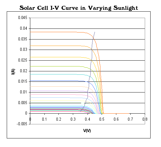 PV solar panel I-V curves example.
” data-medium-file=”https://hackaday.com/wp-content/uploads/2022/07/Solar-Cell-IV-curve-with-MPP.png?w=400″ data-large-file=”https://hackaday.com/wp-content/uploads/2022/07/Solar-Cell-IV-curve-with-MPP.png?w=526″ loading=”lazy” class=”size-medium wp-image-546178″ src=”https://hackaday.com/wp-content/uploads/2022/07/Solar-Cell-IV-curve-with-MPP.png?w=400″ alt=”PV solar panel I-V curves example.” width=”400″ height=”365″ srcset=”https://hackaday.com/wp-content/uploads/2022/07/Solar-Cell-IV-curve-with-MPP.png 526w, https://hackaday.com/wp-content/uploads/2022/07/Solar-Cell-IV-curve-with-MPP.png?resize=250,228 250w, https://hackaday.com/wp-content/uploads/2022/07/Solar-Cell-IV-curve-with-MPP.png?resize=400,365 400w” sizes=”(max-width: 400px) 100vw, 400px”>
The goal of a power-point tracker is to resist the flow of current out of the solar cell so that it’s operating at an intermediate current and voltage that maximizes its output: opening the valve so that the water pushes a water wheel as fast as possible.
It is this simplicity that also hides the complexity of MPPT: in the case of a PV solar panel, its MPP will continually change as solar irradiation changes due to passing clouds, the changing angle of the Sun, and many other factors. This means that the MPP has to be continuously updated, which means determining the optimal voltage with minimal under- or overshoot. Over the years, a number of different approaches to solve this problem have been developed.
While some variations and custom MPPT algorithms exist, the following are the most popular algorithms.
Constant Voltage
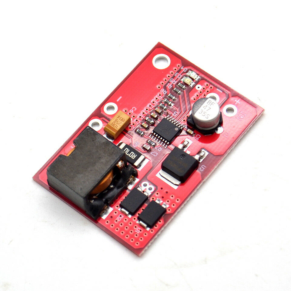 A generic CN3722 constant voltage MPPT board.
” data-medium-file=”https://hackaday.com/wp-content/uploads/2022/07/cn3722_breakout.jpg?w=400″ data-large-file=”https://hackaday.com/wp-content/uploads/2022/07/cn3722_breakout.jpg?w=625″ loading=”lazy” class=”size-medium wp-image-546189″ src=”https://hackaday.com/wp-content/uploads/2022/07/cn3722_breakout.jpg?w=400″ alt=”A generic CN3722 constant voltage MPPT board.” width=”400″ height=”400″ srcset=”https://hackaday.com/wp-content/uploads/2022/07/cn3722_breakout.jpg 960w, https://hackaday.com/wp-content/uploads/2022/07/cn3722_breakout.jpg?resize=250,250 250w, https://hackaday.com/wp-content/uploads/2022/07/cn3722_breakout.jpg?resize=400,400 400w, https://hackaday.com/wp-content/uploads/2022/07/cn3722_breakout.jpg?resize=625,625 625w” sizes=”(max-width: 400px) 100vw, 400px”>
One of the earliest and most basic MPPT algorithms, Constant Voltage (CV) tracking, changes the output current to maintain a constant reference voltage. This approach uses a set fraction of the open circuit voltage, usually around 80%, which means that technically it does not track the MPP at all.
It is still a useful approach because of its simplicity, but it offers low efficiency and suffers in situations where the solar panel is poorly situated and doesn’t see full sun. The low requirements makes it an ideal target for low-cost single-chip solutions, such as the ubiquitous MPPT ICs from Consonance-Elec, such as the CN3722 and CN3791.
A basic 5 A CV MPPT board can be obtained in a variety of generic guises for often less than $10. This makes them ideal for hobby and cost-sensitive applications where efficiency isn’t paramount, and a loosely approximated MPP is sufficient.
Perturb And Observe
This MPPT algorithm is a fairly straight-forward true tracking algorithm. As the name suggests this algorithm is based around the slight nudging of the MPP current set point, measuring current and voltage, determining whether the power produced increased or decreased, and repeating the nudge accordingly.
While quite efficient even in this basic form, the main issue with the perturb and observe algorithm is that it tends to oscillate around the MPP, which will reduce the overall efficiency.
In order for this algorithm to determine whether it needs to adjust the MPP set point, it has to change this set point so that it can observe the effect of this change in the form of the output power. Although this will track the optimal MPP, it will constantly oscillate around it. Here making the adjustment step size as small as possible may seem like a reasonable optimization, but this leads to the system responding very slowly when a rapid change occurs, such as a cloud obscuring the PV panel.
This approach is a good intermediate solution between the simplistic constant voltage approach and something yet fancier.
Incremental Conductance
Incremental conductance measures the changes in current and voltage to predict the effect of a voltage change using the system’s conductance (ΔI / ΔV) — the slope of the power curve. Where perturb and observe takes fixed-size steps and tests if they’re in the right direction, incremental conductance modifies the step size depending on how far away from optimal it is. This has the effect that when it’s already at the MPP, the step size goes to zero and it simply sits there.
Calculating the slope — the ratio of changes in voltage and current — is more sensitive to error than measuring the levels themselves. So while incremental conductance uses a better optimization strategy, it also comes with the most severe hardware requirements, including precision components and a controller that can constantly perform the required calculations. This makes it a good choice for an application where efficiency is paramount, and the available budget generous enough to accommodate the extra expense.
Only The Beginning
The preceding is only a minimal primer on MPPT and the three most common algorithms, and the devil is in the details. For instance, in both the optimization methods, what happens if a bird passes over just as you’ve perturbed the setpoint or taken a voltage step? You might erroneously conclude that the change you made caused the decrease in power. Temperature and other real-world conditions also play a part, so what works on paper may not in practice — helping to explain the persistance of the constant voltage method.
But none of this is so complicated that you shouldn’t implement your own MPPT controller. One such example is found for the STM32F334 microcontroller in Application Note 5324 (AN5324), which details the software and circuitry required to use the high-resolution timer and other peripherals like the ADC and embedded opamp in this MCU to implement what is essentially a perturb-and-observe algorithm that controls an LLC switching mode converter.
While an off-the-shelf MPPT controller is probably the best choice for any project where things should Just Work™, they also form one of those intriguing devices that are simultaneously very simple and as complicated as you want them to be, making them for an excellent hobby project idea.

